Product:
Instructions for use
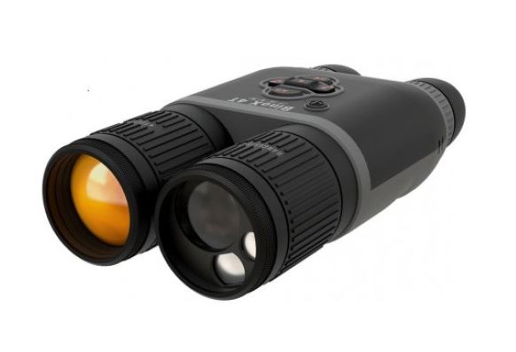
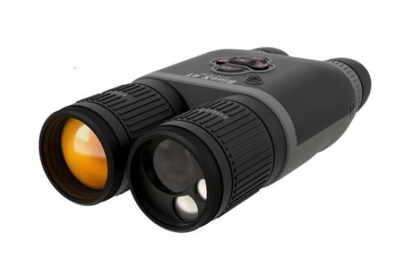
We congratulate you on your new Victory NV 5.6 x 62 T* night vision device with reticule.
Carl Zeiss brand products are characterised by outstanding optical performance, accurate processing and long durability. Please observe the following instructions for use, so that you enjoy optimum use of your product and it can be a faithful companion to you for many years.
Caution
Do not use the night sight to look at the sun or at laser light sources. The image intensifier tube can sustain considerable damage.
Avoid pointing your night sight (also in switched off status) towards the sun or strong sources of light without the objective lens cover and/or without objective lens.
Using the night sight in daylight without objective lens cover or without objective lens can similarly result in damage to the image intensifier tube.
Information for your safety

Caution
Use only battery types recommended by the manufacturer. Handle used batteries in accordance with the manufacturer’s instructions. Under no circumstances should batteries be thrown into a fire, heated up, recharged, taken apart or broken open
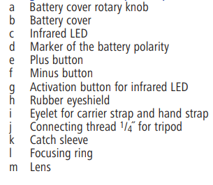
Designation of the component parts


Scope of delivery
● Victory NV night vision device with 5.6 x 62 T* lens
● Eyepiece protection cover
● Lens cover
● Carrier strap
● Hand strap
● 2 x 1.5 V AA batteries
● Carrier bag with carrier strap
Inserting and changing the batteries
The energy supply of the night vision device is provided by 2 batteries, 1.5 V Type AA.
Corresponding rechargeable batteries can also be used instead of the enclosed 1.5 V AA monocells.
To insert and change the batteries, open and remove the battery cover (Fig.1/b) by turning the knob (Fig. 1/a) to the left (anti-clockwise). On the underside of the device (Fig. 2/d), directly below the battery chamber, you can find the specification for the polarity locations of the batteries. Insert the batteries according to these specifications.
Replace the battery compartment cover (Fig.1/b), again using slight pressure, and shut it with a right turn (clockwise) of the rotary knob (Fig. 1/a) to the stop.
Using batteries or rechargeable batteries with different power characteristics may result in different operating times.
When using of non-rechargeable batteries (1.5 V/2600 mAh), an operating time of up to 80 hours can be achieved (without infrared LED). When using rechargeable batteries (1.2 V/750 mAh), the operating time can be reduced to 26 hours (without infrared LED).
Depending on the application conditions, such as for example low temperatures or switching on the infrared LED, the operating time can also be significantly reduced.
If the device is not used for a long time, the batteries should be removed in order to prevent any damage caused by leakage of the batteries. Only use high-quality, brand-name batteries or rechargeable batteries.
Attaching the carrier strap and the hand strap
Eyelets for attaching the carrier strap and the hand strap are provided on both sides of the device. Depending on the type of use, right-hand or lefthand operation, the hand strap can be attached on the right or left side of the device.
For operation with the right hand, one end of the carrier strap is first attached into the eyelet on the left side (Fig. 5/i) of the night vision device, according to Fig. 6.
Attach hand strap according to Fig. 7 – 9 in the eyelets (Fig. 5/i) on the right-hand side of the night vision device. With the belt loop, the hand strap can be adjusted individually to the size of the hand. Stow the belt and belt loop in the hand strap and close hand strap with the two snap fasteners.
Attach the second end of the carrier strap to the hand strap in the eyelet (Fig. 8/n), according to illustration Fig. 10.
For operation with the left hand, the hand strap is attached on the left-hand side of the night vision device, and the free end of the carrier strap on the right-hand side of the night vision device.
Attaching the lens and eyepiece protective covers
The lens and eyepiece protective covers are provided with a cord, and can be attached to the night vision device as represented in Fig. 11.
The lens cover is attached to the free belt eyelet of the night vision device and the eyepiece protection cover is attached to the carrier strap.
Observing with and without spectacles
The night vision device can be used both with and without spectacles and the full visual field is offered in both cases.
For use with spectacles, the rubber eyeshield is inserted (Fig. 3/h). For use without spectacles, the rubber eyeshield is removed (Fig. 4/h).
Both end positions are provided with a latching mechanism.
Operational start-up
Caution!
Daylight and strong sources of light can cause damage to the image intensifier tube! For this reason, the night vision device should never be switched on in daylight without putting on the lens cover (Fig. 11/o) or without lens (Fig. 5/m).
- Switching on: Press “plus key” (Fig. 3/e) for approx. 1 second.
- Switching off: Press “plus key” and “minus key” (Fig. 3/e + f) simultaneously for approx. 1 second.
The intensity of the image intensifier tube can be increased in switched-on status with the plus key (Fig. 3/e) and decreased with the minus key (Fig. 3/f), and thus adapted to the respective lighting conditions. The intensity of the image intensifier tube is set to a medium value each time it is switched on.
Adjustment of the eyepiece (dioptre compensation)
The night vision device is equipped with a reticule (Fig. 10) for the determination of distances. The focussing of the crosshair is implemented by rotating the rubber eyeshield (Fig. 5/h).
A turn to the right (clockwise) corresponds to an adjustment in the minus range, a turn to the left (anti-clockwise) corresponds to an adjustment in the plus range (Range of adjustment ≥ ± 4 dioptres).
A cam is provided on the rubber eyeshield for orientation in darkness. If this is pointed perpendicular upwards, the dioptre compensation is in the zero setting position.
Adjustment to different distances (focusing)
Focusing to different distances is achieved using the lens.
A turn of the focusing ring (Fig. 5/l) to the left (anti-clockwise) corresponds to an adjustment toward infinity. The infinity-focus position is reached when the flat surface of the focusing ring (Fig. 5/l) is vertically above infinity character (∞). Focusing on close objects is done with a right-hand rotation (clockwise) of the adjusting ring. The shortest close-up focus adjustment is approx. 5 m.
Integrated auxiliary lighting (infrared LED)
In the close-up range with a very low level of residual light, the auxiliary lighting (Fig. 2/c) infrared LED can be switched on by activating the button (Fig. 3/g). This auxiliary lighting is only effective in the close-up range.
By pressing the third button (Fig. 3/g) once, the auxiliary lighting (infrared LED) is switched on. By pressing this button again, it is switched off.
The LED is also switched off when the device is switched off.
Removing and attaching the lens
Caution!
In order to avoid damage to the image intensifier tube, the lens may only be changed when the device is switched-off. Avoid any direct incidence of light on the entry surface of the image intensifier tube.
The lens (Fig. 5/m) is connected to the basic device with a C-mount thread. For protection against unintentional unscrewing of the lens, this is secured with a catch ring (Fig. 5/k).
Slide the sleeve (Fig. 5/k) forward in the direction of the focusing ring (Fig. 5/l), and loosen and unscrew the lens (Fig. 5/m) with a left-hand turn (anti-clockwise).
To screw in the lens (Fig. 5/l), the catch sleeve (Fig. 5/k) must be located in the end position in the direction of the focusing ring (Fig. 5/l). Screw in the lens to the limit stop and insert the catch sleeve (Fig. 5/k) into the mating toothed section of the housing.
The lens is screwed in correctly if the “Carl Zeiss” lettering is at the top of the lens.
Observing with the night vision device
After switching on and adjusting the eyepiece, you can focus on different distances using the focusing ring on the lens. This function is limited if observation is done in daylight with the protective cap on.
The intensity of the image intensifier tube is set to the medium amplification range when it is switched on. You can adapt the intensity of the image intensifier tube to the respective lighting conditions with the “Plus” and “Minus” buttons.
In case of extended observations of a location, a camera tripod (Carl Zeiss tripod; order no.: 1206-889) is a useful addition. Here, the night vision device can be screwed onto the tripod using the tripod thread (Fig. 5/j).
The tripod thread (Fig. 5/j) is designed so that tripods both with a 1/4˝ and 3/8˝ screw thread can be used. When using a tripod with 3/8˝ screw thread, the 1/4˝ adapter is unscrewed with a coin.
Protective shutdown
The night vision device is equipped with a protective shutdown so that the batteries will not completely discharge
If the supply voltage falls below a defined value, the device switches off automatically. The device can be restarted; however it automatically switches off again after approx. 10 sec.
The batteries should be replaced immediately after activation of protective shutdown.
Determination of distance using the reticule
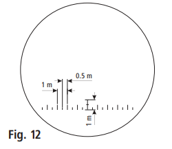
For distance determination, a reticule (Fig. 12) is integrated into the night vision device on the eyepiece side.
All dimensions in metres with reference to 100 m distance.
The distance between the intervals at 100 m distance is 1 m, and 0.5 m between sub-intervals.
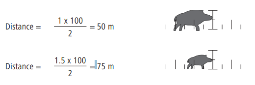
Determination of the distance in case of known length/width or height of the object:
- Example:
Assuming a wild boar with a length of about 1 m fits between 2 intervals of the reticule (Fig. 13), the distance is as follows:
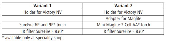
Accessories and spare parts
Auxiliary lighting
For use at greater distances, a holder is provided to attach a torch of brand names “SureFire” or “Maglite” (using adapter) with attachable IR filter on the Victory NV.
Maintenance notes
Your night vision device from Carl Zeiss does not require any special maintenance. However, careful handling is rewarded with impeccable appearance, continuous operability and a long service life.
Do not wipe coarse dirt particles (e.g. sand) from the lens, rather blow them away or remove with a camel hair brush!
Fingerprints can attack the lens surface after some time. Breathing on the lens surface and wiping off with a clean optical cleaning cloth is the simplest way to clean.
Protect the device as much as possible against the action of grease and oilcontaining materials. Dirt and fingerprints can be eliminated easily with pure alcohol (no acetone) and a clean cloth.
The battery compartment and the battery compartment cover should always be kept clean and dry.
Technical data