Products:
- https://www.optics-trade.eu/en/schmidt-bender-3-12×50-pm-ii.html
- https://www.optics-trade.eu/en/schmidt-bender-3-12×50-pm-ii-p.html
- https://www.optics-trade.eu/en/schmidt-bender-4-16×42-pm-ii-lp.html
- https://www.optics-trade.eu/en/schmidt-bender-4-16×42-pm-ii-lp-double-turn-1-4-moa.html
- https://www.optics-trade.eu/en/schmidt-bender-3-20×50-pm-ii-ultra-short.html
- https://www.optics-trade.eu/en/schmidt-bender-pm-ii-10×42.html
- https://www.optics-trade.eu/en/schmidt-bender-3-20×50-pm-ii-lp-mtc-lt.html
- https://www.optics-trade.eu/en/schmidt-bender-3-27×56-pm-ii-high-power.html
- https://www.optics-trade.eu/en/schmidt-bender-5-25×56-pm-ii-lp-mtc-lt-ral8000.html
- https://www.optics-trade.eu/en/schmidt-bender-5-25×56-pm-ii-lp-mtc.html
- https://www.optics-trade.eu/en/schmidt-bender-5-25×56-pm-ii-lp-mtc-lt-pantone.html
- https://www.optics-trade.eu/en/schmidt-bender-5-25×56-pm-ii-lp-mtc-lt.html
- https://www.optics-trade.eu/en/schmidt-bender-12-50×56-pm-ii-p.html
- https://www.optics-trade.eu/en/schmidt-bender-3-20×50-pm-ii-lp-mtc-lt-ral8000.html
- https://www.optics-trade.eu/en/schmidt-bender-3-20×50-pm-ii-lp-mtc-lt-pantone.html
- https://www.optics-trade.eu/en/schmidt-bender-3-27×56-pm-ii-high-power-ral8000.html
- https://www.optics-trade.eu/en/schmidt-bender-3-27×56-pm-ii-high-power-pantone.html
- https://www.optics-trade.eu/en/schmidt-bender-5-20×50-pm-ii-ultra-short.html
- https://www.optics-trade.eu/en/schmidt-bender-5-20×50-pm-ii-ultra-short-pantone.html
- https://www.optics-trade.eu/en/schmidt-bender-3-12×50-pm-ii-lp-27035.html
- https://www.optics-trade.eu/en/schmidt-bender-3-12×50-pm-ii-lp-mtc.html
- https://www.optics-trade.eu/en/schmidt-bender-3-12×50-pm-ii-p-tactical-rifle-scope.html
- https://www.optics-trade.eu/en/schmidt-bender-4-16×50-pm-ii-lp-27161.html
- https://www.optics-trade.eu/en/schmidt-bender-4-16×42-pm-ii-lp-27171.html
- https://www.optics-trade.eu/en/schmidt-bender-3-12×50-pm-ii-lp-mtc-1-focal-plane-ffp-1cm-100m-0-1mrad-gen2-cw.html
1. Introduction. . . . . . . . . . . . . . . . . . . . . . . . . . . . . . . . . . . . . . . . . . . . . . 8
2. Safety instructions. . . . . . . . . . . . . . . . . . . . . . . . . . . . . . . . . . . . . . . . . 8
3. Adjusting the image focus with the diopter adjustment of the eyepiece. . 8
4. Mounting the scope to a firearm . . . . . . . . . . . . . . . . . . . . . . . . . . . . . . . 8
4.1 General information. . . . . . . . . . . . . . . . . . . . . . . . . . . . . . . . . . . . . 8
4.2 Adjustment range and forward angle. . . . . . . . . . . . . . . . . . . . . . . . . 8
4.3 Preliminary adjusting and fine adjusting when sighting in. . . . . . . . . 9
5. Function of the „double turn“ turret . . . . . . . . . . . . . . . . . . . . . . . . . . . 10
6. Function of the „multi turn“ turret. . . . . . . . . . . . . . . . . . . . . . . . . . . . 10
7. Function of the „MTC“ turret. . . . . . . . . . . . . . . . . . . . . . . . . . . . . . . . . 11
8. Determining individual values for bullet drop compensation. . . . . . . . . . 11
9. Parallax adjustment. . . . . . . . . . . . . . . . . . . . . . . . . . . . . . . . . . . . . . . 11
10. Using the illumination control . . . . . . . . . . . . . . . . . . . . . . . . . . . . . . . . 11
11. Changing the battery. . . . . . . . . . . . . . . . . . . . . . . . . . . . . . . . . . . . . . 12
12. Maintenance. . . . . . . . . . . . . . . . . . . . . . . . . . . . . . . . . . . . . . . . . . . . 12
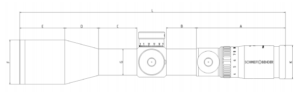
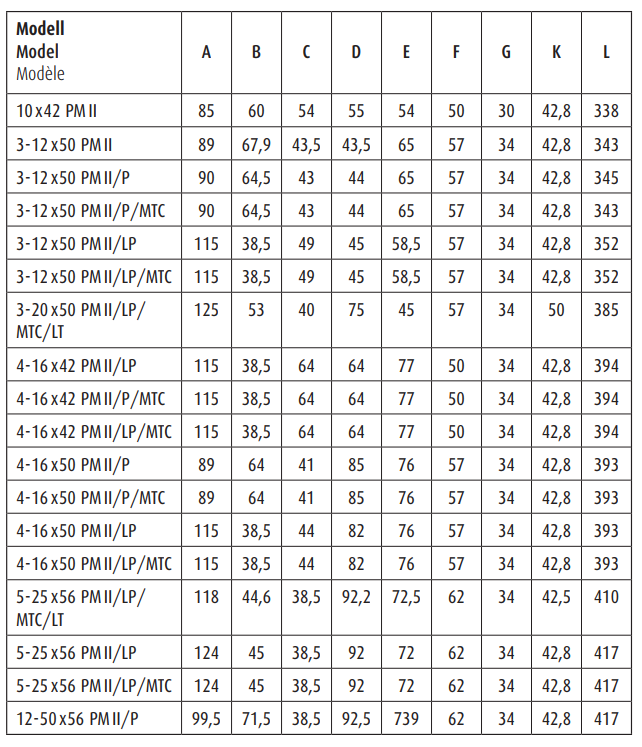
13. Dimensions of PMII scopes. . . . . . . . . . . . . . . . . . . . . . . . . . . . . . . . . . 19
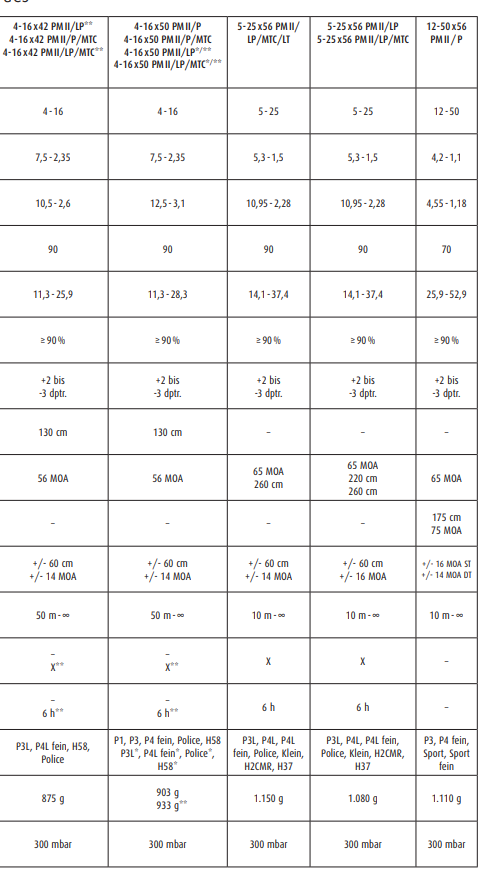
14. Technical data. . . . . . . . . . . . . . . . . . . . . . . . . . . . . . . . . . . . . . . . . . . 20
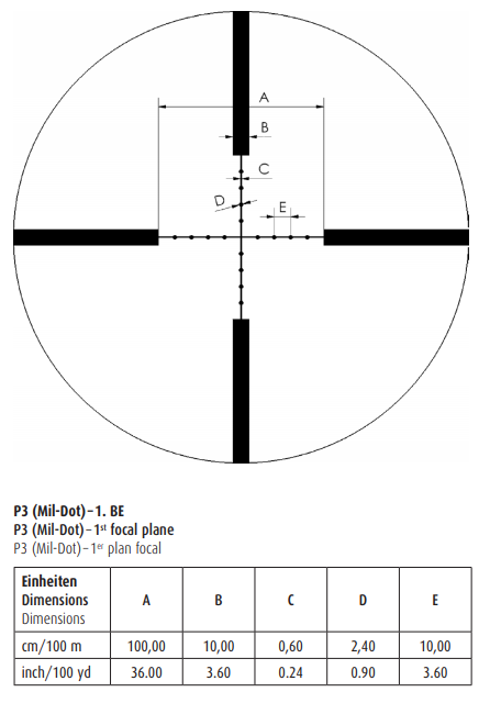
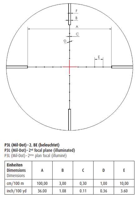
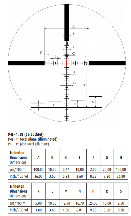
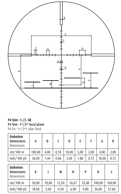
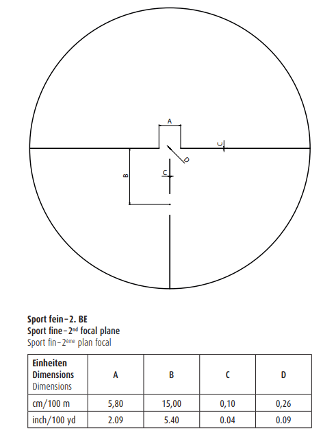
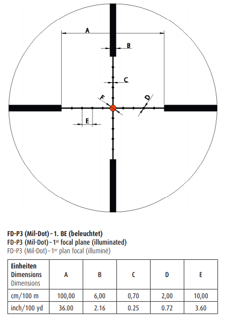
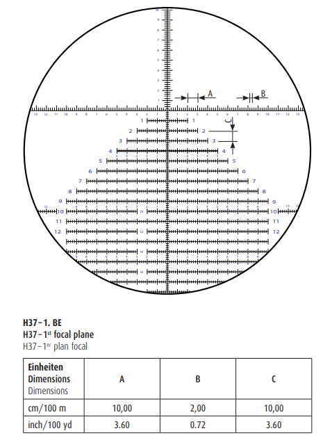
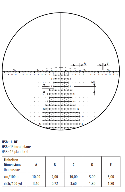
15. Reticles. . . . . . . . . . . . . . . . . . . . . . . . . . . . . . . . . . . . . . . . . . . . . . . . 22
16. Warranty Certificate. . . . . . . . . . . . . . . . . . . . . . . . . . . . . . . . . . . . . . . 40
1. Introduction
The scopes of the Schmidt&Bender PMII series are designed to meet the unique challenges of high precision shooting. Their quality and function make it possible to achieve exceptional shooting results as well as to fulfill the critical and demanding needs of official, law enforcement and tactical applications. Strict observation of the following operating instructions is prerequisite for successful long-term use.
2. Safety instructions
Never look into the sun with the scope. This may cause serious eye injuries. To avoid injuries always keep the correct eye relief distance when shooting. Do not tamper with the scope. Any repairs going further than the maintenance described in the maintenance manual should only be done by Schmidt&Bender or by other specialists authorized by Schmidt&Bender. Protect the scope against shocks beyond normal use.
Avoid unnecessarily long exposure of the scope to direct sunlight; intense and excessive sun radiation will cause extremely high temperatures inside the tube which may be detrimental to the scope.
3. Adjusting the image focus with the diopter adjustment of the eyepiece
Set the scope to the highest magnification. Rotate the eyepiece counterclockwise to its stop. Rotate the eyepiece clockwise until you see a sharp image of the reticle (see illus. 1).
4. Mounting the scope to a firearm
4.1. General information
The firearm and the scope must be united by proper mounting. Therefore we recommend to get this done by a qualified specialist. Perfect mounting is an essential requirement for maximum accuracy and an efficient functioning of the firearm and the scope.
Be sure to assume the proper firing position and keep a correct eye relief in order to avoid any injuries due to the recoil of the weapon. To mount the 10 x42 PMII, the 1-8 x24 PM ShortDot, the 1.1-4 x20 PM ShortDot, the 1.1-4 x24 PM ShortDot LE and the 1.5-6 x20 PM ShortDot scope you need rings with a 30 mm diameter. All other PMII scopes will require 34 mm rings. The mount should be rugged and of good quality. For safety reasons we recommend that the lower part of the rings should be glued.
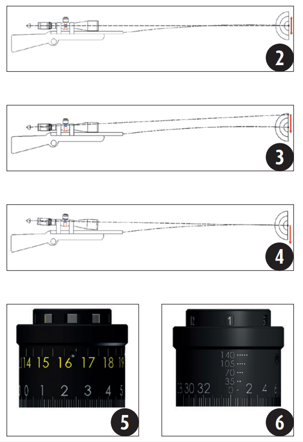
4.2. Adjustment range and forward angle
Scopes for high precision shooting are often used for shooting at great distances. In this case the elevation adjustment is used to compensate for bullet drop. To obtain an even greater adjustment range on these scopes, Schmidt&Bender increased the diameter of the center tube on a number of precision scopes for long distances from 30 to 34 mm. Nevertheless, elevation and windage ranges are limited like in any other scope.
To get a consistent adjusting range in every direction and to simplify the mounting procedure, the reticle on the scopes is usually set to the optical and mechanical center position (see illus. 2).
To be able to use the complete elevation adjustment on the PMII scopes it is absolutely necessary to realize a default adjustment on the reticle outside the optical and mechanical center position (illus. 3). Therefore the gunsmith is forced to adjust the default value during scope mounting, i.e. the scope should be mounted on the firearm using the proper forward angle (illus. 4). Using this setting the entire adjustment range may be used in one direction. Thus, depending on caliber and scope design, you may shoot the weapon at greater distances.
Determining the proper forward angle
The necessary forward angle is depending on the used type of elevation adjustment. At the Schmidt&Bender factory the reticles of PMII scopes are adjusted out of center by half the amount of the full elevation range. This value must be compensated in the mount system. Forward angled mounts or rails for every Schmidt&Bender PMII scope type are available from all renowned mount manufacturers.
Example for determining the required forward angle
A standard elevation turret (single turn) with an elevation range of 13 mrad (equals 130 cm at 100 m distance) requires a forward angle of 65 cm at 100 m (equaling half the full elevation range). A gunsmith compensating for this value using the mounts should observe the following rule of thumb: If the space between the two mount rings is 100 mm, the front mount should be 0.65 mm lower than the rear mount.
If the gunsmith is using a rail with forward angle, he may use standard mount rings without forward angle.
4.3. Preliminary adjusting and fine adjusting when sighting in
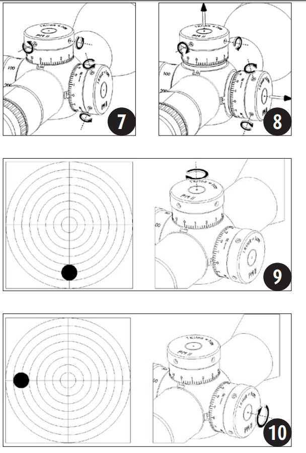
Make sure that both elevation and windage are set to -0-. If the scope is equipped with a „double turn“ elevation turret, the windows on top of the turret must show black (see illus. 5). The „multi turn“ turret has to show -1- (illus. 6). Mount the scope to the firearm and pre-adjust the scope to a target at 100 m distance using all adjustment facilities the mounts provide so that the least possible amount of elevation range must be used at the scope for fine adjustment. Before sighting in unlock the two setscrews in the outside diameter of both elevation an windage turret using an Allen key (see illus. 7). Lift each turret cap until the black o-ring underneath is visible. Lock the setscrews again (see illus. 8). The turret caps may not be adjusted in all directions for fine adjustment.
With every click the reticle will travel by the amount indicated on the turret cap. A too low point of impact is corrected by rotating the elevation turret clockwise (see illus. 9), a too high point of impact by rotating the elevation turret counter-clockwise.
A too far left point of impact is corrected by rotating the windage turret clockwise (see illus. 10), a too far right point of impact is corrected by rotating the turret counter-clockwise.
Attention: for counter-clockwise elevation and windage versions the corrections for point of impact must be effected in the opposite directions!
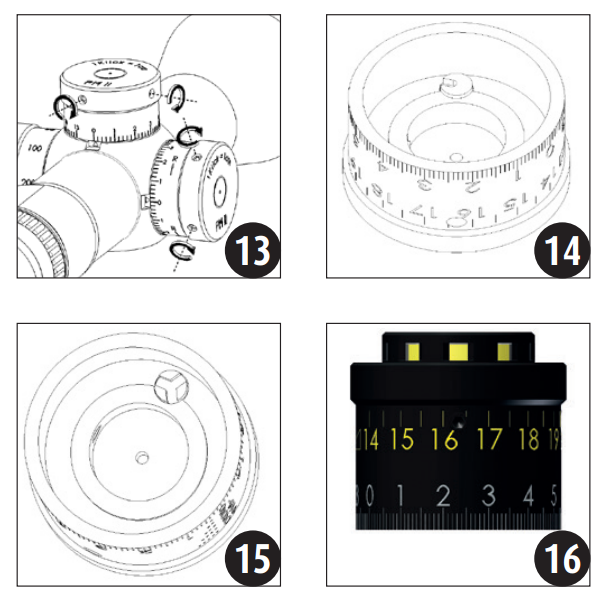
After sighting in, loosen the two Allen screws inside the turrets (illus. 11). Then reset elevation and windage adjustments to -0-, corresponding to the indexing triangle on the respective tube position. Make sure the turrets do not rotate (and change the position of the reticle) while doing this. Press the turret caps completely down (see illus. 12) and lock the setscrews again (see illus. 13).
When the scope is equipped with a „double turn“ elevation turret make sure that the color in the windows on top of the turret cap is still showing black (see illus. 5). If the color changed to yellow proceed as follows: unlock the setscrews in the outside diameter of the „double turn“ turret again, pull the turret cap up and take it off completely. Position the slotted steel cylinder (see illus. 14) inside the turret cap in its final position (a screw driver or similar tool may be used to rotate the cylinder). Choose the position providing for the windows on top of the turret cap to show black. Now place the turret cap on the elevation turret again as described before.
The „multi-turn“ turrets should still show -1- (illus. 6). If not, proceed as follows: loosen Allen screws and remove turret cap. Now return the pendular cylinder (illus. 15) using a screwdriver, if necessary, to its basic position. Now put the turret cap back on the scope as described above.
5. Function of the „double turn“ turret
The „double turn“ elevation provides a fine click adjustment value with a big elevation adjustment range at the same time. Instead of having only one revolution for the full elevation range the „double turn“ turret – as the name implies – uses two revolutions for the full elevation range. As described in the chapter „preliminary adjusting and fine adjusting when sighting in“ the elevation gets sighted in and is thus set to -0-. Starting from this position you may use the complete elevation range. If elevation is set to a position within the first revolution, the windows on top of the turret cap show black (see illus. 5) indicating the shooter must refer to the lower scale on the turret cap. If the turret is rotated into the second revolution the windows change their color to yellow (see illus. 16), clearly indicating that elevation is in the second revolution and the shooter now must refer to the yellow scale. Even in poor light conditions the shooter may easily recognize in which revolution the turret is set at every given time and thus to what value the elevation is set.
6. „Multi turn“ function
The „multi turn“ version of our turrets permits a fine click lock adjustment while keeping a wide adjustment range at the same time. Instead of only one turn the „multi turn“ feature may achieve a total of five turns. As we described in chapter „preliminary adjusting and fine adjusting when sighting“, the turret is sighted in once and set on top of the zero position. Starting from this position the shooter may now use the large adjustment range of the „multi turn“ function. If you find yourself in the first rotation (illus. 6), -1- is displayed in the windows on top of the turret. If you proceed and rotate to the second 11 12 13 14 15 5 6 16 5 6 11 English rotation, -2- will appear. The second rotation starts with the adjustment above zero. The two engraved dots beside this number indicate that you find yourself in the second rotation. The same applies for the 3rd, 4th and 5th rotation (illus. 17).
7. „MTC“ Function (More Tactile Clicks)*
Turrets featuring the optional „MTC“ (Schmidt & Bender, U.S. Patent # 7.612.952) function have a stronger lock on every 10 clicks on the elevation and windage adjustment.
Various other models only have a stronger lock on the windage zero position.
8. Determining individual values for bullet drop compensation
By shooting at varying distances and recording the corresponding click values in a table you can make your own individual bullet drop compensation charts. In contrast to the common technique of calibrating adjustment turrets to „predetermined“ trajectory tables provided by ammunition manufacturers our recommended procedure takes all factors into account that have a influence on bullet drop – firearm, mount and used ammunition. This will result in extremely precise bullet drop tables created specifically for your firearm.
9. Parallax adjustment
All PMII models without parallax adjustment are preset at the Schmidt&Bender factory to be parallax-free at 300 m unless a different distance is specified.
PMII scopes with parallax compensation have an easily operable setting wheel (illus. 18), positioned as a third turret opposite the windage adjustment. With this turret the shooter may easily focus targets at any distance without having to interrupt his target acquisition.
The parallax adjustment turret is engraved with distance markings. If the distance to the target is known rotate the turret so that the corresponding distance marking lines up with the index mark on the saddle.
If the distance to the target is not known set the scope to the highest magnification. Then move the adjustment ring of the parallax compensation in the direction of the estimated distance until you get a focused image.
Not he parallax has been properly adjusted and you may also read the distance on the turret.
10. Using the illumination control
The illuminated reticle is designed to help identifying the correct aiming point on a dark target and/or in poor light conditions.
First, set the intensity of the illuminated reticle to the respective light conditions. To do this the illumination control may be turned from -0- toward position -11- until a setting is achieved where the illuminated portion of the reticle is just bright enough to be picked up by the eye without glaring. If possible, this adjustment should be performed under quiet conditions prior to the actual shooting. To save battery power the illumination may now be switched off by a slight turn of the illumination control halfway between the chosen and the next setting (before or after the chosen setting). In this interposition the power supply is interrupted („stand-by mode“, see illus. 19). Immediately before shooting the illumination control may now be turned back on and the reticle will now illuminate using the proper intensity. If the illumination is not switched off by the shooter after use, illumination control electronics automatically switch off the illumination after 6 hours.
11. Changing the battery
To replace the battery screw off the battery cap and remove the old battery. Please discard the used battery in an ecologically compatible way! Place the new battery (coin cell CR 2032/3V) with the „+“ facing up into the battery compartment. Do only change the battery in a dry environment. Battery service life is a minimum 100 hours at the highest intensity (see illus. 20).
12. Maintenance
Schmidt&Bender PMII scopes do not require any special maintenance. All metal parts have a hard anodized surface that is extremely scratch-resistant and easy to care for. For cleaning use a clean and, if necessary, a slightly damp cloth.
For cleaning the optics please use the included Schmidt & Bender cleaning kit. Before wiping the optic’s surfaces, use a dry brush to remove coarse dirt or dust particles. Slight impurities may then be wiped off using an optic’s cleaning cloth. Breathe onto the optic’s surfaces before cleaning them, this should help with the cleaning process. Excessive dirt may be removed using the cleaning liquid included in the cleaning kit.
Avoid dry rubbing on the outside optical surfaces, this may harm the precious coatings.


Warranty Certificate
We hereby certify that our Quality Management System has been approved by Unternehmensgruppe TÜV Rheinland Berlin Brandenburg to the following Quality Management Standard: The TÜV Cert Certification Body of TÜV Anlagentechnik GmbH (Unternehmensgruppe TÜV Rheinland Berlin Brandenburg) certifies in accordance with TÜV Cert procedures that Schmidt&Bender GmbH & Co. KG, Am Grossacker 42, D- 35444 Biebertal has established and applies a quality management system for the design, production sales and service of fine mechanical optical instruments. Main product telescopic sights. Proof has been furnished that the requirements according to DIN ISO 9001:2000 – # Registration No. 01 100 67280 – are fulfilled.
All parts have been thoroughly inspected in accordance with the afore-mentioned Quality Management System and correspond to the requirements of the specifications, drawings, test procedures and standards in all respects.
Guarantee clause:
Official legal guarantee period of 2 years (according to the EU rules
Schmidt&Bender GmbH & Co. KG
Am Grossacker 42
35444 Biebertal
Germany
Material supplied:
Schmidt&Bender telescopic sight / scope label