Product:
Operating Manual 3-27×56 PMII High Power
1. Scope description………………………………………………………………………………5
1.1 Introduction ………………………………………………………………………………….. 5
1.2 Safety instructions…………………………………………………………………………. 5
2. Technical data…………………………………………………………………………………..6
2.1 General data………………………………………………………………………………… 6
2.2 Dimensions……………………………………………………………………………………. 6
3. Accessories / Scope of supply……………………………………………………………7
4. Operating instructions ………………………………………………………………………..7
4.1 Adjusting the image focus with the diopter adjustment of the
eyepiece…………………………………………………………………………………………………… 8
4.2 Parallax adjustment………………………………………………………………………. 8
4.3 Illumination control ……………………………………………………………………….. 9
4.4 Changing the battery…………………………………………………………………. 10
4.5 Using the reticle for the distance estimation ………………………………. 10
5. Point of impact correction ………………………………………………………………..13
5.1 Using the elevation turret and the windage turret…………………….. 13
5.2 Preliminary adjusting and fine adjusting when sighting in…………… 15
5.3 Elevation adjustment ………………………………………………………………….. 16
5.4 Windage adjustment ………………………………………………………………….. 17
6. Maintenance……………………………………………………………………………………18
6.1 Using the scope covers……………………………………………………………….. 18
6.2 Care and maintenance……………………………………………………………… 18
6.3 Storage temperature ………………………………………………………………….. 18
7. Warranty certificate………………………………………………………………………….19
1. Scope description
1.1 Introduction
The Schmidt & Bender PM II series scopes are designed to meet the unique challenges of high precision shooting. Their quality and function make it possible to achieve exceptional shooting results as well as to fulfill the critical and demanding needs of official, law enforcement and tactical applications. Strict observation of the following operating instructions is prerequisite for successful long-term use.
1.2 Safety instructions
Never look into the sun or into laser light with the scope. This may cause serious eye injuries. Do not tamper with the scope. Any repairs beyond the maintenance described in the maintenance manual should only be performed by Schmidt & Bender or by other specialists authorized by Schmidt & Bender. Protect the scope against shocks beyond normal use.
Avoid unnecessary long exposure of the scope to direct sunlight; intense and excessive sun radiation will cause extremely high temperatures inside the tube which may be detrimental to the scope.
The scope must be properly mounted to the firearm by a qualified specialist. Perfect mounting is an essential requirement for maximum accuracy and efficient functioning of the firearm and the scope. Be sure to assume the proper firing position and keep a correct eye relief in order to obtain an optimal full field of view and to avoid any injuries due to the recoil of the weapon.
2. Technical data
2.1 General data
- Magnification – 3x – 27x
- Objective lens diameter – 56 (mm)
- Field of view – 13 – 1, 5 (m/100m)
- Exit pupil – 8,7 – 2,1 (mm)
- Eye relief distance – 90 (mm)
- Twilight factor – 8,8 – 38,9
- Transmission – 90 (%)
- Diopter adjustment – +2 to -3 (dptr)
- Parallax adjustment – 10 – ∞ (m)
- Weight – 1130 (g
2.2 Dimensions

3. Accessories / Scope of supply
Some of the listed accessories are delivered with the scope while optional accessories are marked with a (*). All parts can be ordered by the listed part numbers.
Lens Cleaning Kit – 971-90
Objective cap(*) – 971-638
Killflash (*) – 971-632
Sunshade black (*) – 917-4565
Sunshade RAL 8000 (*) – 917-4565-45
Sunshade Pantone (*) – 917-4565-46
Yellow filter (*) – 149-421
Grey filter (*) – 148-421
2mm allen key – 400-23
Transport bag RAL 8000 (small) (*) – 971-084
Transport bag black (small) (*) – 971-085
Registration card, Reply card, Scope label
4. Operating instructions

4.1 Adjusting the image focus with the diopter adjustment of the eyepiece
The eyepiece provides the adjustment of the reticle focus to the individual eye diopter. Set the scope to the highest magnification. Rotate the eyepiece counterclockwise until it stops. Rotate the eyepiece clockwise until you see a sharp image of the reticle (see Illustr. 3).

4.2 Parallax adjustment
The 3-27×56 PMII scope provides parallax compensation with an easily operable setting wheel (Illustr. 4), positioned as a third turret opposite the windage adjustment. With this turret the shooter may easily focus targets at any distance without having to interrupt his target acquisition.
The parallax adjustment turret is engraved with distance markings. If the distance to the target is known rotate the turret so that the corresponding distance marking lines up with the index mark on the saddle.
If the distance to the target is not known set the scope to the highest magnification and then move the adjustment ring of the parallax compensation in the direction of the estimated distance until you obtain a focused image. Now the parallax has been properly adjusted and you may also read the distance on the turret.

4.3 Illumination control
The illuminated reticle is designed to help identifying the correct aiming point on a dark target and/or in poor light conditions.
First, set the intensity of the illuminated reticle to the respective light conditions. To do this the illumination control may be turned from -0- toward position -11- until a setting is achieved where the illuminated portion of the reticle is just bright enough to be picked up by the eye without glaring. If possible, this adjustment should be performed under quiet conditions prior to the actual shooting. (see Illustr. 5)
If the illumination is not switched off by the shooter after use, illumination control electronics automatically switch off the illumination after 2 hours.
If the illumination starts blinking, the battery is low and should be replaced.

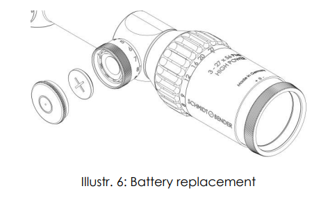
4.4 Changing the battery
To replace the battery screw off the battery cap and remove the old battery.
Please discard the used battery in an ecologically compatible way!
Place the new battery (coin cell CR 2032/3V) with the „+” facing up into the battery compartment. Do only change the battery in a dry environment. Battery service life is at least 100 hours at the highest intensity (see Illustr. 6).
4.5 Using the reticle for the distance estimation
The different available reticles offer a variety of possibilities to estimate or measure important parameters by means of reticle subtensions. This allows the shooter to place highly precise shots even on large distances by use of the estimates, the ballistic compensator and the parallax adjustment.
The reticle is in the first focal plane such that the reticle subtensions remain constant on all magnifications.
Exemplary for the P4F reticle in the first focal plane (see picture below) the distance “B” of the large tics corresponds to 10cm/100m. The shooter can thus calculate the distance to a target which size is known by measuring it with the reticle pattern: If a 10cm sized target fits inbetween two large tics, it is positioned in a distance of 100m.
For arbitrary object sizes and distances a relation exists according to the following formula:

Whereas
? is the distance to the target,
? is the estimated size of the target,
? is the size of the target on the reticle pattern.
According to the measured distance, the parallax can be set and the bullet drop can be compensated by the elevation turret.
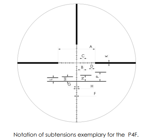
The reticle subtensions for your reticle can be found in the catalog or on the available datasheets.
5. Point of impact correction
5.1 Using the elevation turret and the windage turret
Elevation turret – Lockable Double Turn Turret with More Tactile Clicks
The elevation turret includes the following features:
- Double turn
- MTC (more tactile click)
- Zero Stop
- Locking function
The elevation turret provides a fine click adjustment value in addition to a large elevation adjustment. When the turret is rotated into the second revolution a small cylinder pops up on top of the turret which indicates to the user that the second turret revolution has been reached. (See Illustr. 7)

The zero stop function supports the quick adjustment to the zero position. The zero stop function is determined by an end stop.
The MTC (more tactile click) elevation turret has an audible “clunk” on every 10th click.
The elevation turret includes a locking function which prevents the inadvertent adjustment of the turret. To lock the turret, the outer flange with the engraving must be pushed down in direction of the scope tube until “LOCKED” appears on the turret (Illustr. 8) To unlock the turret, the outer flange must be pulled up until the “LOCKED” indicator completely disappears (Illustr. 8).

Windage turret – Lockable Single Turn Turret with Zero Stop
The windage turret includes the following features:
- Single turn
- MTC (more tactile click)
- Zero Stop
- Locking function
The windage turret locking function works basically the same as on the elevation turret. (see Illustr. 8)
The windage turret has one positive “clunk” at the zero position which provides a “0” reference point.
5.2 Preliminary adjusting and fine adjusting when sighting in
When sighting in the scope for the first time, or re-sighting the scope due to service or repair, a test shoot for zeroing the scope must be performed on a 100m distance. Therefore, ensure that the parallax is set to the correct value of 100m and that both elevation and windage turrets are set to “0”. The double turn turret must be set to the first revolution.
The centering of the target pattern is then performed according to paragraph 5.3 and 5.4.
Lock the elevation turret, loosen the two setscrews on the outside diameter in line with the “LOCKED” indicator using an Allen key (see Illustr. 9). Unlock the turret by pulling up the outer flange and turn the turret until the engraved “0” is indicated by the triangle on the saddle. Lock the elevation turret by pushing down the outer flange with the engraving and tighten the two setscrews with an Allen key.
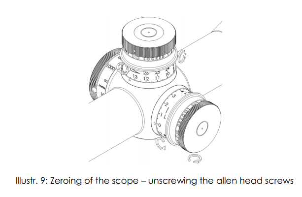
To zero the windage turret lock the windage turret, loosen the two setscrews on the outside diameter in line with the “LOCKED” indicator using an Allen key (see Illustr. 9). Unlock the turret by pulling up the outer flange and turn the turret until the engraved “0” is indicated by the triangle on the saddle. Lock the windage turret by pushing down the outer flange with the engraving and tighten the two setscrews with an Allen key.
- The turrets are secured by an additional third slotted screw which should only be removed when completely replacing the turret due to damage.
- The turret clicks can still be felt and heard when the screws are unlocked. This has no impact on the process of zeroing as the thread piece does not move while the setscrews are loose.
5.3 Elevation adjustment
Depending on the configuration, the point of impact is moved by either 0.1mrad (1cm on 100m) or ¼ MOA with every click. A too low point of impact is corrected by rotating the elevation turret counter-clockwise (see Illustr. 10), a too high point of impact by rotating the elevation turret clockwise.
For clockwise rotating turrets this relation is opposite!

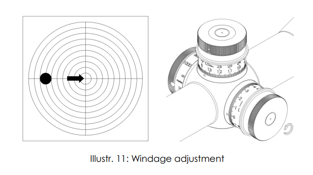
5.4 Windage adjustment
Depending on the configuration, the point of impact is moved by either 0.1mrad (1cm on 100m) or ¼ MOA. A too far left point of impact is corrected by rotating the windage turret counter-clockwise, a too far right point of impact is corrected by rotating the turret clockwise (see Illustr. 11).
For clockwise rotating turrets this relation is opposite!
6. Maintenance
6.1 Using the scope covers
To protect the scope and its lenses against adverse environmental conditions like sand, dust, rain, snow, etc., the protective flip-up caps of objective and eyepiece should be closed after every use of the scope. Before shooting, make sure that the caps are open.
6.2 Care and maintenance
Schmidt & Bender PM II scopes do not require any special maintenance. All metal parts have a hard anodized surface that is extremely scratch-resistant and easy to care for.
For cleaning outer surfaces, use a clean and, if necessary, a slightly damp cloth.
For cleaning the optics use the included Schmidt & Bender cleaning kit.
Before wiping the optic’s surfaces, use a dry brush to remove coarse dirt or dust particles. Slight impurities may then be wiped off using an optic’s cleaning cloth.
Breathe onto the optic’s surfaces before cleaning them, this helps with the cleaning process. Excessive dirt may be removed using the cleaning liquid included in the cleaning kit.
Avoid dry rubbing on the outside optical surfaces, this may harm the precious coatings.
6.3 Storage temperature
The approved temperature range for the storage of the scope is from -55°C to 70°C.
7. Warranty certificate
We hereby certify that our Quality Management System has been approved by Unternehmensgruppe TUV Rheinland Berlin Brandenburg to the following Quality Management Standard: The TUV Cert Certification Body of TUV Anlagentechnik GmbH (Unternehmensgruppe TUV Rheinland Berlin Brandenburg) certifies in accordance with TUV Cert procedures that Schmidt & Bender GmbH & Co. KG, Am Grossacker 42, D- 35444 Biebertal has established and applies a quality management system for the design, production sales and service of fine mechanical optical instruments. Main product telescopic sights. Proof has been furnished that the requirements according to ISO 9001 – # Registration No. 01 100 67280 – are fulfilled. All parts have been thoroughly inspected in accordance with the afore-mentioned Quality Management System and correspond to the requirements of the specifications, drawings, test procedures and standards in all respects.
Guarantee clause:
Official legal guarantee period of 2 years (according to the directive of EU)
Contact:
Schmidt & Bender GmbH & Co. KG • Am Grossacker 42 • D-35444 Biebertal •Germany
Tel. +49 (0) 64 09-81 15-0 • Fax +49 (0) 64 09-81 15-11
[email protected] • www.schmidt-bender.de
Schmidt & Bender Inc. • 741 Main Street • Claremont, NH 03743 • U.S.A.
Tollfree (800)468-3450 • Phone +1(603)287-4830 • Fax (603)287-4832
[email protected]