Product:
Pulsar Axion KEY XM22 Thermal Imaging Monocular: https://www.optics-trade.eu/en/pulsar-axion-key-xm22-thermal-imaging-monocular.html
This text is a transcription of the file in PDF format.
SPECIFICATIONS
| SKU# | 77424 | 77425 |
| AXION KEY Model | KEY XМ22 | KEY XМ30 |
| Microbolometer | ||
| Type | uncooled | uncooled |
| Resolution (pixels) | 320×240 | 320×240 |
| Frame refresh rate (Hz) | 50 | 50 |
| Pixel size (microns) | 12 | 12 |
| Optical specifications | ||
| Optical magnification (x) | 2 | 2,5 |
| Smooth digital zoom (x) | 2-8 | 2.5-10 |
| Digital zoom (x) | 2/4 | 2/4 |
| Relative aperture (D/f) | 1.2 | 1.2 |
| Minimum focusing distance (m/y) | 11 (12) | 3 (3.28) |
| Exit pupil diameter (mm/inch) | 3 | 3 |
| Angle of field of view (HxV), degrees | 10 | 7,3 |
| Angle of field of view, metres at 100m | 17.5 | 12.8 |
| Focusing range of eyepiece (dioptres) | -4/+5 | -4/+5 |
| Detection distance (deer type object), m (y) | 950 | 1300 |
| Display | ||
| Type | LCOS | LCOS |
| Resolution (pixels) | 960х720 | 960х720 |
| Operational specifications | ||
| External power voltage | 3 – 4.2 V | 3 – 4.2 V |
| Battery type | Li-Ion Battery Pack АPS3 | Li-Ion Battery Pack АPS3 |
| Capacity | 3200 mAh | 3200 mAh |
| Rated output voltage | DC 3.7 V | DC 3.7 V |
| External power supply | 5 V (USB) | 5 V (USB) |
| Battery charge life in hours (at 22°C) | 4 | 4 |
| IP code (IEC60529) degree of protection | IPХ7 | IPХ7 |
| Operating temperature range | -10°С … +40°С/+14F … +104F | -10°С … +40°С/+14F … +104F |
| Dimensions (mm/inch) | 143x41x69/5.63х1.61х2.71 | 149x49x70/5.87х1.93х2.75 |
| Weight without batteries (kg/oz) | 0.25/8.82 | 0.27/9.52 |
Improvements may be made to the design and software of this product to enhance its user features.
The current version of the User manual may be found on the website www.pulsar-vision.com
DELIVERY PACKAGE
- AXION KEY Thermal Imager
- APS3 rechargeable battery
- Power adapter
- USB cable
- Case
- Hand strap
- Quick start guide
- Cloth for cleaning optics
- Warranty card
DESCRIPTION
AXION KEY IR-matrix (microbolometer) based thermal imaging monoculars are represented by a number of models that differ in magnification and lens diameter. These devices are designed for use both at night-time and during the day in difficult weather conditions (fog, smog, rain), as well as where obstacles are present that impede the detection of a target (branches, tall grass, dense shrubs etc.). Unlike night-vision devices that are based on electron-optical converters, thermal vision monoculars do not require an external light source and are resistant to the effects of bright light.
AXION KEY monoculars can be used for night-time hunting, observation and terrain orientation, and carrying out rescue operations.
DISTINGUISHING FEATURES
- High magnification
- Long detection distance
- High-contrast HD Display.
- Microbolometer pixel size of 12 microns
- Various colour palettes
- Stadiametric rangefinder
- IPX7 completely waterproof
- Convenient user interface
- Strengthened metal body
- Short power-up time (quick start)
- Lightweight and compact
- Functional and ergonomic design
- Three calibration modes (manual, semi-automatic and automatic)
- Three observation modes (forest, rocks and identification)
- Picture in picture (PiP) function
Battery Pack - Quick-change APS3 Li-ion battery pack
- USB charging option
COMPONENTS AND CONTROLS
- Eyepiece dioptre adjustment ring
- Down button

- Menu button
- Up/Zoom button
- On/Calibration ON button
- Lens focus ring
- Lens cap
- MicroUSB connector
- Battery release button
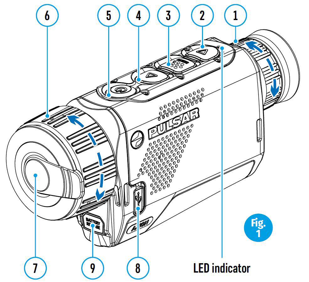
LED indicator displaying current status of the device
| LED Indicator | Operating Mode |
| Device is powered on | |
| Device on / battery charge <10% |
For a better viewing experience, we recommend that glass wearers fold back the edge of the elastic eyeshade.
BUTTON OPERATION
| Control mechanism | Condition / Operating Mode | 1 short press | Next short press | Long press |
| ON button
|
Device is powered off | Power on the device | Device calibration | Power on the device |
| Display off | Turn on display | Device calibration | Power off the device | |
| Device turned on, quick menu, main menu | Device calibration | Display off / device powered off |
||
| Up/Zoom button
|
Device is powered on | Change magnification (Zoom) | PiP on/off | |
| Quick menu | Increase parameter | Increase parameter | ||
| Main menu | Navigation up, right | Navigation up, right | ||
| Menu button
|
Device is powered on | Open quick menu | Open main menu | |
| Quick menu | Navigation up | Exit quick menu | ||
| Main menu | Confirm value, enter menu options | Exit menu options, exit main menu |
||
| Down button
|
Device is powered on | Operating modes | Color palettes | |
| Quick menu | Reduce parameter | Reduce parameter | ||
| Main menu | Navigation down, left | Navigation down, left |
USING THE RECHARGEABLE BATTERY
AXION KEY thermal imagers are supplied with a rechargeable APS3 Lithium-ion Battery Pack. The battery should be charged before first use.
Charging the battery
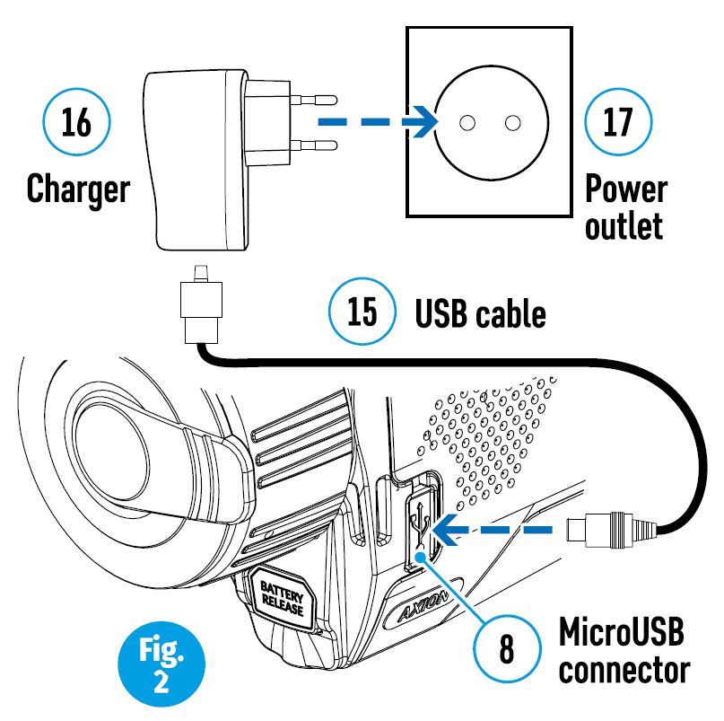
Option 1 (Fig.2):
- Install the battery (10) into its slot on the instrument case (14) by aligning the icons to form a ‘dot’ on the device and the battery. (see Fig. 4).
- Attach a USB cable (15) to the microUSB connector (8) on the device.
- Connect the other end of the USB cable (15) to the mains charger (16) or to a USB socket connected to another power source with rated output of 5V or less.
- Connect the mains charger (16) to the mains power supply.
Note: The PB8I Power Bank may be used as a charger (see Item 7).
Option 2 (Fig.3):
- Insert the rechargeable battery (10) supplied with your device, or purchased separately, fully along the guide rail into the APS charger slot (аvailable separately) (11).
- Point A on the battery and Point B on the charger should be aligned.
- Two batteries can be charged at the same time – a second slot is provided for this.
- Attach the USB plug on the USB cable (15) to the USB connector on the mains device (16). Plug the deviceinto a 100–240 V power outlet (17).
- Attach the second plug of the microUSB cable to the socket (12) of the mains charger (11).
- The LED indicator (13) will light up battery charge status (see table).

Battery charge status (see table).
| LED Indicator * | Battery charge status |
| Battery charge from 0% to 10%; Charger not connected to the mains power supply. | |
| Battery charge from 0% to 10%; Charger connected to the mains power supply. | |
| Battery defective. Battery should not be used. | |
| Battery charge from 10% to 20%. | |
| Battery charge from 20% to 60%. | |
| Battery charge from 60% to 95%. | |
| Battery completely charged. Can be disconnected from the charger. |
* The LED indicator displays the current level of charge of the battery for 30 seconds when the APS charger is not plugged in. When the power is connected, the display shows the current status of the battery constantly the LEDs additionally flickering to indicate the battery charging process.
Installation:
- Insert the battery (10) into the assigned slot on the device casing (14), aligning the images on the instrument and the battery.
- When properly installed, the battery is locked into the slot with a special clip.
- To remove the battery, press the Battery Release button (9).

Safety measures:
- When charging, always use the charger supplied with your optical device. The use of a different charger may cause irreparable damage to the battery or the charger and may cause the battery to ignite.
- After being stored for a long time, the battery should be partially charged – it should not be fully charged or completely discharged.
- Do not charge the battery immediately after bringing it from the cold into a warm atmosphere. Wait 30–40 minutes for the battery to warm up.
- Do not leave the battery unattended during charging.
- Do not use the charger if it has been modified or damaged.
- The battery should be charged at a temperature of between 0° C and +45° C, otherwise the battery life will be significantly reduced.
- Do not leave a charger with a battery connected to the mains for more than 24 hours after full charge.
- Do not expose the battery to high temperatures or naked flame.
- The battery is not intended to be immersed in water.
- The connecting of third-party devices with an energy consumption greater than permissible is not recommended.
- The battery is equipped with a short circuit protection system. However, situations that may lead to short circuiting should be avoided.
- Do not dismantle or deform the battery.
- Do not subject the battery to shocks or falls.
- Where the battery is used in below-zero temperatures, capacity will decrease. This is normal and does not indicate a defect.
- Do not use the battery in temperatures that exceed those shown in the table – this may shorten battery life.
- Store the battery out of the reach of children.
EXTERNAL POWER SUPPLY
External power is supplied from an external source, such as a 5V Power Bank.
- Attach the external power source to the device’s USB connector (8) (Fig. 1)
- The device will switch to operation from the external power source, while the APS3 battery will be gradually recharged.
- An icon of a battery will appear on the display showing its charge as a percentage.
- If the device is operated from an external power source and the APS3 battery is not connected, an icon is displayed .
- When the external power supply is disconnected, the device switches to the internal power supply without the device powering off.
OPERATION
ATTENTION! The lens of the device must not be pointed at any sources of intense energy, such as laser-emitting devices or the sun. This may damage the electronic components in the device. Damage caused by failure to comply with the operating guidelines is not covered under warranty.
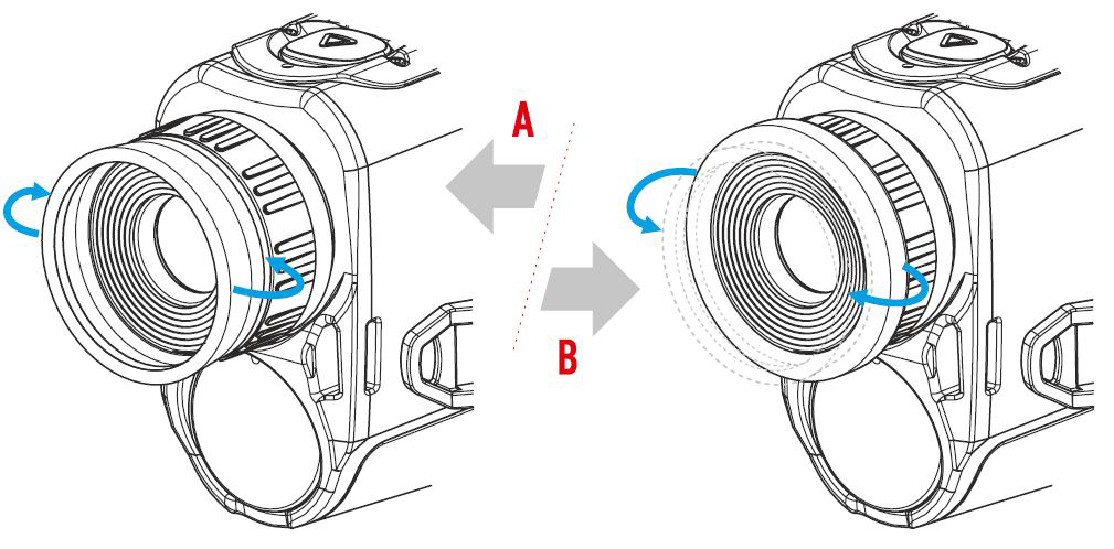
Switching on and adjusting the image
- Remove the lens cover (7). Secure the cover to the strap using the magnet built into the cover.
- Power up the device by pressing the ON button (5).
- Adjust the resolution of the icons on the display by rotating the dioptre adjustment ring on the eyepiece (1). In future, it will not be necessary to rotate the eyepiece dioptre adjustment ring, regardless of distance and other conditions.
- To focus on the object being observed, rotate the lens focus ring (6). Axion XM22 does not require lens focusing.
- Adjustment of brightness and contract in the display, as well as turning on the smooth digital zoom, are described in the FAST ACCESS MENU FUNCTIONS section.
- Turn the device off after use with a long press of the ON button (5).
CALIBRATING THE SENSOR
Calibration enables the microbolometer temperature background to be equalised and defects in the image (such as vertical lines, phantom images etc.) to be eliminated.
There are three calibration modes: manual (M), semi-automatic (SA) and automatic (A). Select the required mode in the CALIBRATION section of the menu ![]() .
.
- M mode (manual). Secure the lens cap and briefly press the ON button (5). After completing the calibration process, remove the lens cap.
- SA mode (semi-automatic). Calibration is engaged by a brief press of the ON button (5). The lens cap need not be secured (the sensor is closed by an internal shutter).
- A mode (automatic). The device is calibrated autonomously, in accordance with the software algorithm. The lens cap need not be secured (the sensor is closed by an internal shutter). In this mode, the device may be calibrated by the user using the ON button (5) (in semi-automatic mode).
DISCRETE DIGITAL ZOOM
The device’s functionality offers the possibility of quickly increasing its base multiplicity (see the table of technical properties in the Digital Zoom line) by a factor of 2 or 4. Adjust the digital zoom accordingly by pressing the DOWN button (2).
THE QUICK ACCESS MENU FUNCTIONS
The basic settings (brightness and contrast adjustment, use of the smooth digital zoom function and the stadiametric rangefinder) are changed via the Quick Access Menu.
- Enter the menu with a short press of the Menu button (3).
- A short press of the Menu button (3) enables you to switch between functions.
Brightness ![]() – by pressing the UP (4) / DOWN (2) buttons and changing the display brightness value from 00 to 20.
– by pressing the UP (4) / DOWN (2) buttons and changing the display brightness value from 00 to 20.
Contrast ![]() – by pressing the UP (4) / DOWN (2) buttons and changing the display contrast value from 00 to 20.
– by pressing the UP (4) / DOWN (2) buttons and changing the display contrast value from 00 to 20.
Smooth digital zoom ![]() – by pressing the UP (4) / DOWN (2) buttons and changing the digital zoom value from 1.0 to 4.0. The increment size of the digital zoom is 0.1.
– by pressing the UP (4) / DOWN (2) buttons and changing the digital zoom value from 1.0 to 4.0. The increment size of the digital zoom is 0.1.
To exit the menu, press and hold down the Menu button (3), or wait 10 seconds for automatic selection. The initial smooth digital zoom factor displayed is equal to x1.0 if the discrete zoom is inactive, x2.0 if is 2x, and x4.0 if 4x.
Note. Current magnification is calculated as the product of the base magnification and the smooth digital zoom ratio. Example: where the basic device magnification is 3.0x and the smooth digital zoom ratio is x1.7, the actual magnification is 5,1х (3,0*1,7). The next time the device is turned on, the image is projected onto the display with the brightness and contrast settings saved from the previous power off.
Stadiametric rangefinder ![]() – press the UP (4) / DOWN (2) buttons to change the position of the markings for determining the distance of the object being observed (see Section 16 for further information on the rangefinder).
– press the UP (4) / DOWN (2) buttons to change the position of the markings for determining the distance of the object being observed (see Section 16 for further information on the rangefinder).
MAIN MENU FUNCTIONS
- Enter the menu with a long press of the Menu button (3).
- Press the UP (4) / DOWN (2) buttons to move through the menu functions.
- Menu navigation is be means of scrolling. When the last item on the first tab is reached, navigation moves to the first item of the second tab.
- One short press of the Menu button (3) opens a menu item.
- To exit the menu, press and hold down the Menu button (3).
- Automatic exit from the menu occurs after 10 seconds of inactivity.
- When exiting the menu, the cursor location () is remembered only for the duration of the one working session (i.e. until the device is powered off). The next time the device is powered on and the menu is accessed, the cursor will be at the first item on the menu.
General view of the menu
Tab 1

Tab 2

Composition and description of the menu
| Mode | The devices have three operating modes: FOREST (observation mode of objects within low thermal contrast conditions), IDENTIFICATION (high zoom mode), ROCKS (observation mode of objects within high thermal contrast conditions). Each mode has been created to provide the best image quality of a wild nature object being observed within various observation conditions.
ROCKS MODE
|
| Calibration Mode
|
Selection of calibration mode There are three calibration modes: manual, semi-automatic and automatic.
Automatic |
| Icon brightness
|
Adjusting icon brightness.
|
| General Settings
|
This menu item allows you to program the following settings |
| Language
|
Choose Language
|
| Date
|
Setting the Date
|
| Time
|
Setting the Time
|
| Units of Measurement
|
Selecting a unit of measurement
|
| Default Settings
|
Restore Factory Settings
|
| Removal of Defective Pixels
|
When using the device, defective (broken) pixels may appear on the sensor: i.e. bright or dark points of constant brightness that are visible on the image. AXION KEY thermal imagers offer the possibility of removing any defective pixels on the sensor programmatically, as well as to cancel any deletion.
|
| Return to factory ‘pixel map’ |
Return all defective pixels previously disabled by the user to their original state:
|
STATUS BAR
The status bar is located at the bottom of the display and displays information relating to the operational status of the device, including:
- Observation mode
- Calibration mode (when in automatic calibration mode with 3 seconds remaining until automatic calibration, a countdown timer will appear in place of the calibration icon).
- Current full magnification
- USB connection (if the device is connected)
- Colour palette (displayed only when the Hot Black palette is installed)
- Current time
- Battery discharge level (when the device is powered by the rechargeable battery)
- External power supply indicator (when the device is powered from an external supply)
![]() Note: when calibration is in progress, the display image freezes for the duration of the calibration
Note: when calibration is in progress, the display image freezes for the duration of the calibration
STADIAMETRIC RANGEFINDER
Thermal imagers are fitted with a stadiametric rangefinder that enables the distance to an object to be defined where its size is known.
- The stadiametric rangefinder function is accessed by a short press of the Menu button (3) and selecting the icon .
- Bars will appear on the display to determine the distance, icons of three objects and digits of the estimated distance of these three objects.
There are three pre-set values for objects:
Hare – height 0.3 m
Boar – height 0.7 m
Deer – height 1.7 m

- Place the lower fixed cursor beneath the object and, with the UP (4) / DOWN (2) navigation buttons, move the upper horizontal cursor relative to the lower horizontal fixed cursor so that the object is positioned between the cursors. An automatic recalculation of the distance to the target occurs simultaneously with this movement.
- If the distance is not determined within 10 seconds, the information disappears from the display.
- Go to the relevant item on the menu to select a unit of measurement (metres or yards).
- A distance value is rounded up or down before appearing on the display to 5 metres for longer distance readings and 1 metre for shorter distance readings.
- To exit the rangefinder mode, press the Menu button (3) briefly, or wait 10 seconds for automatic exit.
DISPLAY OFF FUNCTION
This function disables the transfer of images to the display, reducing the intensity of its illumination to a minimum. This helps prevent inadvertent unmasking. The device will continue to function.
- When this function is in use, the device switches to standby mode, which allows it to be quickly turned off, if necessary.
- When the device is switched on, press and hold the ON button (5). The display will disappear and the message ‘Display off.’ will appear.
- To switch on the display, press the ON button (5) briefly.
- When the ON button (5) is held, the display will show ‘Display off.’ and a countdown.
Then the device will turn off.
PiP FUNCTION

PiP (Picture in Picture) enables you to view a magnified digital zoom image
in a separate ‘window’ simultaneously with the main image.
Enabling/disabling the PiP function:
- Press and hold the Menu button (3) to enter the main menu.
- Select the ‘PiP Mode’ option
- A short press of the Menu button (3) switches the mode on/off.
- Press and hold the Menu button (3) to exit the main menu.
- The enlarged image is displayed in a separate window using the full optical zoom value.
- To alter the zoom ratio in the PiP window, briefly press the UP button (4).
- The remaining image is displayed with the optical zoom value which corresponds to the value of the x1.0 coefficient.
- When the PiP is turned on, you can control the discrete and smooth zooms. In this instance, the full optical magnification value will appear only in the separate window.
- When PiP is turned off, the image is displayed with the optical zoom value set for the PiP mode.
COLOR PALETTES
The principal display mode for an observed image is ‘Hot White’.
- To enable the alternative palettes described below and to toggle between them, press the DOWN button (2) long.
Colour palettes:
Hot White
A black and white palette (cold temperature corresponds to black, and hot temperature to white).
Hot Black
A black and white palette (cold temperature corresponds to white, and hot temperature to black).
Hot Red
Rainbow
Ultramarine
Sepia
USB CONNECTION
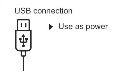
Connecting the device to a computer used as an external power source.
- Connect one end of the USB cable to the device’s microUSB connector (8) and
the other end to the port on your computer. - Switch the device on by pressing the ON button (5) (the computer will not
detect the device if it is turned off). - The device is detected automatically by the computer and no installation of drivers is required.
- When this option is selected, the computer is used by the device as an external power source. An icon will appear in the status bar . The device will continue to function and all functions are available.
- The battery installed in the device will not be charged.
- When disconnecting the USB from the device when connected in Power Mode, the device will continue to function on battery power, if present and sufficiently charged.
- If a video was being recorded at the time of connection, the recording will cease and be saved.
TECHNICAL INSPECTION
A technical inspection of the device is recommended before each use. Check:
- The external appearance of the device (there should be no cracks in the casing).
- The condition of the lens and eyepiece (there should be no cracks, greasy spots, dirt or other deposits).
- The condition of the rechargeable battery (this should be charged) and the electrical contracts (there should be no presence of salts or oxidation).
- The controls should be in working order.
MAINTENANCE
- Maintenance should be carried out at least twice a year and consist of the following actions.
- Wipe the external surfaces of metal and plastic parts free of dust and dirt with a cotton cloth Silicone grease may be used for this.
- Clean the electrical contacts of the battery and battery slot on the unit using a non-greasy organic solvent.
- Check the glass surfaces of the eyepiece and the lens. If necessary, remove dust and sand from the lenses (preferably using a non-contact method). Cleaning of the external surfaces of the optics should be done with substances designed specially for this purpose.
TROUBLESHOOTING
This table lists all the problems that may arise when operating the device. Carry out the recommended checks and repairs in the order shown in the table. If a defect should occur that is not listed in the table, or if it is impossible to repair the defect yourself, the device should be returned for repair.
| Malfunction | Possible reason | Correction |
| Thermal imager does not power up. | Battery completely discharged. | Charge the battery. |
| Does not operate from external power source. | USB cable damaged. | Replace USB cable. |
| External power source discharged. | Charge external power source (if necessary). | |
| Image is unclear, with vertical lines and uneven background. | Calibration required. | Perform image calibration according to Section ‘Operation’ of the Instructions. |
| Image is too dark. | Low brightness or contrast level set. | Adjust brightness or contrast. |
| Coloured lines appeared on display or image has disappeared. | The device was exposed to static electricity during operation | After exposure to static electricity, the device may either reboot automatically, or require turning off and on again. |
| Poor image quality / reduced detection distances. | These problems may occur during observation in difficult weather conditions (snow, rain, fog etc.). | |
| When used in low temperature conditions, image quality of the surroundings is worse than in positive temperature conditions. | In positive temperature conditions, objects being observed (surroundings and background) heat up differently because of thermal conductivity, thereby generating a high temperature contrast. Accordingly, image quality produced by the device will be higher. In low-temperature conditions, objects being observed (background) do, as a rule, cool down to roughly the same temperature, because of which temperature contrast is substantially reduced and image quality (detail) is poorer. This is a feature of thermal imaging devices. | |
By following the link below you can find answers to the most frequently asked questions about thermal imaging https://www.pulsar-nv.com/glo/support/faq/79
![]() Environment protection first!
Environment protection first!
Your appliance contains valuable material which can be recovered or recycled. Leave it at a local civic waste collection point.
![]() Attention! AXION KEY thermal imagers require a licence when exported outside your country.
Attention! AXION KEY thermal imagers require a licence when exported outside your country.
Electromagnetic compatibility.
This product complies with the requirements of European standard EN 55032: 2015, Class A.
Caution: Operating this product in a residential area may cause radio interference.
The term of possible repair of the device is five years.